SECONDARY REFRIGERANT SYSTEMS. |
Home |
Secondary refrigerants | Benefits available from the use of secondary refrigerants | Disadvantages of Secondary Refrigerants | Types and Properties of Secondary Refrigerants | Calcium Chloride Brine | Factors to be considered in selecting a brine | Conversion of Hydrometer readings
Secondary refrigerants |
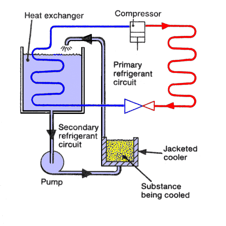
Secondary refrigerants are usually liquids, and are used to transfer heat from the substance being cooled to a heat exchanger where the heat is absorbed by a primary refrigerant. In an air conditioning system it could be said that air is acting as a secondary refrigerant.
These fluids are cooled by a primary refrigerant then exposed to the source, being sensibly heated by that source, thus absorbing its energy, and the warmer fluid returned to the chiller, rejecting the heat to the primary refrigerant.
High temperature applications such as air conditioning use chilled water as the secondary refrigerant while low temperature applications use brines, glycols and oils.
Large refrigeration plants often use secondary refrigerants to transport the cooling capacity from the plant room to the point of use.

A Basic Secondary refrigeration System.
Benefits available from the use of secondary refrigerants:- |
Disadvantages of Secondary Refrigerants:- |
Types and Properties of Secondary Refrigerants |
A good secondary refrigerant should have the following features:
The simplest secondary refrigerant is water, much used in air conditioning work above 0 °C, the corrosion problem is minimal with a closed system. Used where application of control and flexibility allows some expenditure above the minimum.
Obviously, water has its limitations for lower temperature work due to its freezing, but this disadvantage can be overcome by adding a salt to form a brine. In general brines can be divided into four classes:
1 and 2 act on the phenomenon that water with a salt or other soluble material added has a depressed freezing point. The freezing point will obviously depend on the amount of salt in the water (i.e. proportion or concentration of the salt or material in the water. Each mixture has a concentration at which the freezing is a minimum. This concentration is the Eutectic Concentration. The minimum freezing point is the Eutectic Temperature and the point in the Temp/Conc. diagram is the Eutectic point. Two physical change lines exist on either side of the Eutectic Point namely the freezing line and crystallising or solubility line. The freezing line is found by taking a liquid or concentration below the eutectic Concentration, cooling it and in the form of ice, crystals will appear at a certain temperature leaving a liquid of higher concentration. Continued cooling will result in more crystals, further increase of concentration and so on. The freezing line is obtained by joining the respective freezing points.
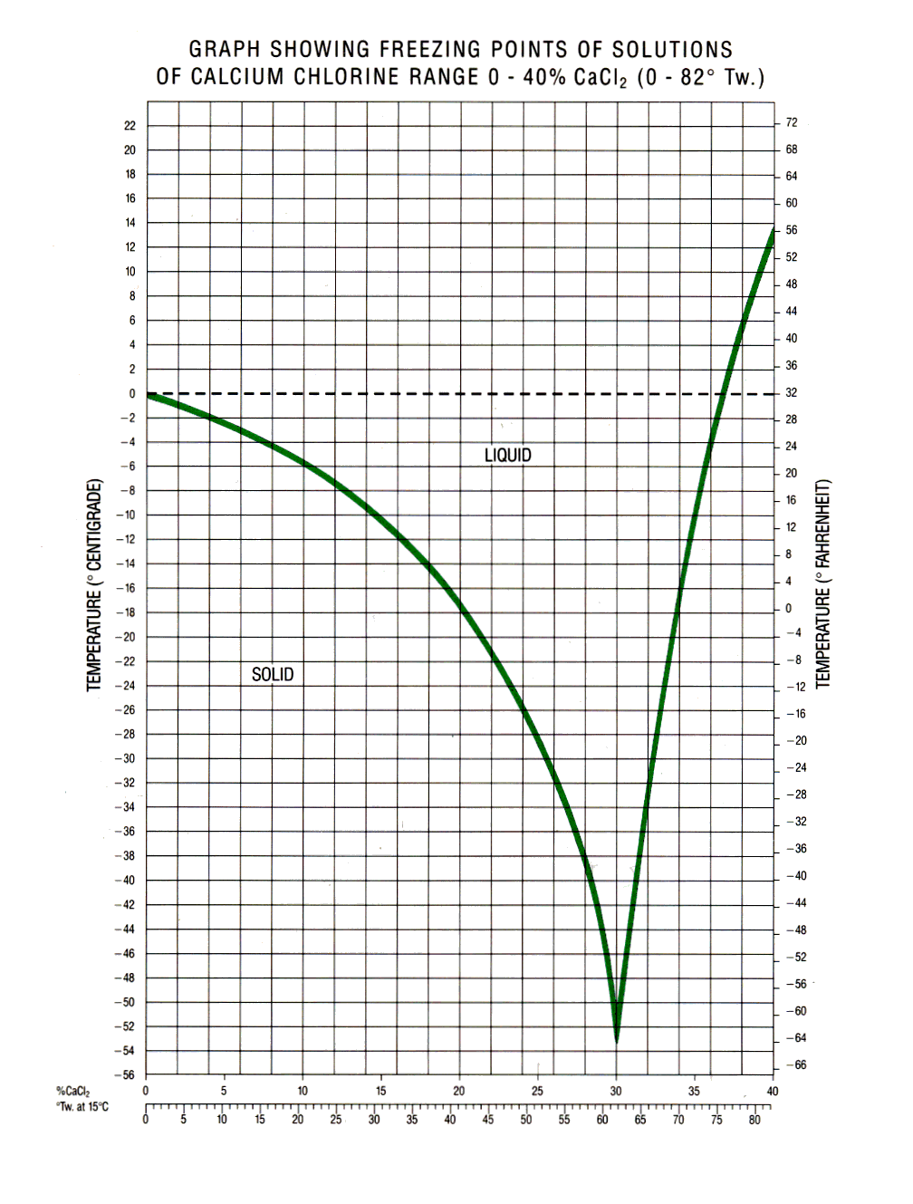
The solubility line is found by taking a liquid sample whose concentration is above the eutectic concentration and cooling it. In this situation salt crystals will form at a certain temperature, reducing the concentration.
Further cooling causes more crystals to form and so on. The crystallising line is obtained by joining the respective points of crystallising. In practice the line around the Eutectic Points are vague and rarely published.
Eutectic points are:
Calcium Chloride Brine |
Calcium chloride brine is the commonest secondary refrigerant used in industrial and marine refrigeration systems.
Water is used for air conditioning installations (with suitable safeguards to prevent its freezing).
The density of the brine solution used has to be increased as the minimum temperature to be used decreases. The freezing point varies as in the table below.
| CALCIUM CHLORIDE / BRINE | |||
Specific Gravity |
Hydrometer Reading (Twaddell) |
Freezing Point of Solution |
|
°C |
°F |
||
1·20 |
40 |
-21 |
-6 |
1·21 |
42 |
-23 |
-9 5 |
1·22 |
44 |
-25 |
-13 |
1·23 |
46 |
-27 |
-17 |
1·24 |
48 |
-30 |
-21.5 |
1·25 |
50 |
-32 |
-26 |
1·26 |
52 |
-35 |
-31 |
1·27 |
54 |
-38 |
-37 |
1·28 |
50 |
-42 |
-44 |
1·29 |
58 |
-51 |
-60 |
In using the Twaddell hydrometer, the brine sample should be at +15°C (60°F) as the instrument is calibrated for use at this temperature.
In the absence of air, calcium chloride is not severely corrosive (steel brine pipes remain in good condition internally, but steel brine header and makeup tanks suffer severe corrosion at the brine/air interface). However, it is desirable to keep the brine slightly alkaline, with pH between 8·0 and 8·5. If found to be acid (e.g. litmus test papers), caustic soda should be added.
Brine heaters contain steam heated coils within a shell through which brine is circulated. When warm brine is required for defrosting, the steam should be put on first and the brine now restricted by first cracking the inlet brine valve until the brine has risen in temperature to above O°C, (32°F). An initial high flow rate of cold brine can cause freezing of the steam condensate with subsequent blockage. A brine temperature of 43°C (110°F) is suitable for defrosting.
Factors to be considered in selecting a brine |
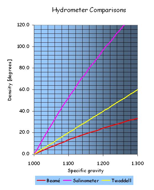
Conversion of Hydrometer readings |

Comparative hydrometer readings |
||||
Specific gravity |
Twaddell [ °Tw ] |
Beaumé [ °Bé ] |
° on Salinometer |
|
1·000 |
0 |
0·0 |
0 |
1,000 |
1·074 |
14·8 |
10·0 |
40 |
1,074 |
1·100 |
20 |
13·2 |
53 |
1,100 |
1·115 |
23 |
15·0 |
60 |
1,115 |
1·125 |
25 |
16·1 |
64 |
1,125 |
1·150 |
30 |
18·9 |
76 |
1,150 |
1·160 |
32 |
20·0 |
80 |
1,160 |
1·175 |
35 |
21·6 |
86 |
1,175 |
1·200 |
40 |
24·2 |
97 |
1,200 |
1·208 |
41·6 |
25·0 |
100 |
1,208 |
1·225 |
45 |
26·6 |
107 |
1,225 |
1·250 |
50 |
29·0 |
116 |
1,250 |
1·261 |
52·2 |
30·0 |
120 |
1,261 |
1·275 |
55 |
31·3 |
125 |
1,275 |
1·300 |
60 |
33·5 |
134 |
1,300 |
Secondary Refrigerant Systems |
The evaporators (brine coolers) pumps and distribution valves in industrial installations and on cargo ships are usually located together within an insulated brine room, to provide ease of access and to eliminate the need for insulating individual items and pipes. Entering a brine room for the first time can be bewildering and consulting the brine diagram of a complex installation may at first increase the bewilderment. However, the system is basically very simple, the complexity arises from duplication of components and alternative cross connections.
The following diagrams attempts to illustrate the development of a brine system.
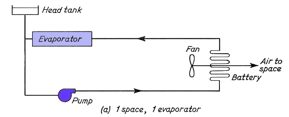
Part (a) above, is the basic diagram with one chamber battery circulated with brine from one evaporator, in a closed circuit with a header tank to allow for expansion and contraction of the brine.
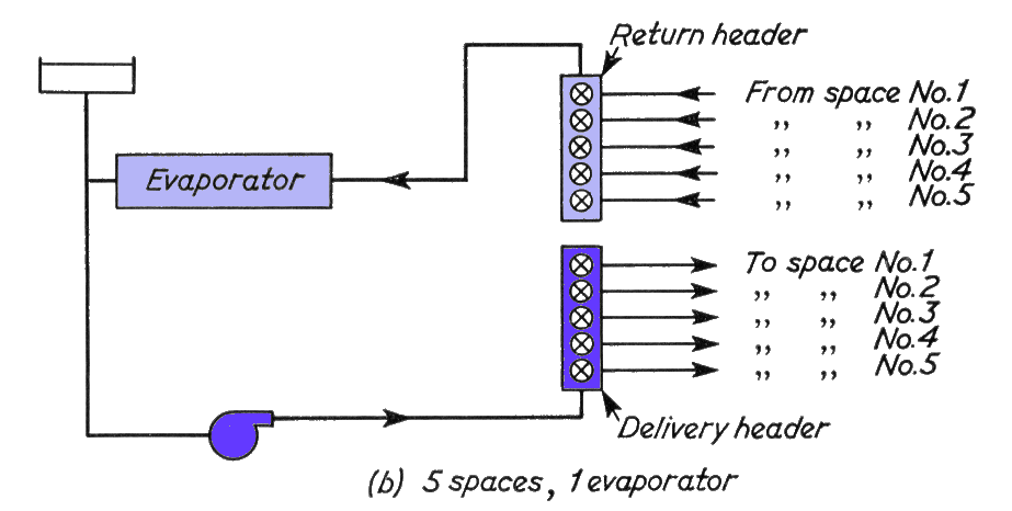
Part (b) above, shows the addition of headers which enable a number of spaces to be served.
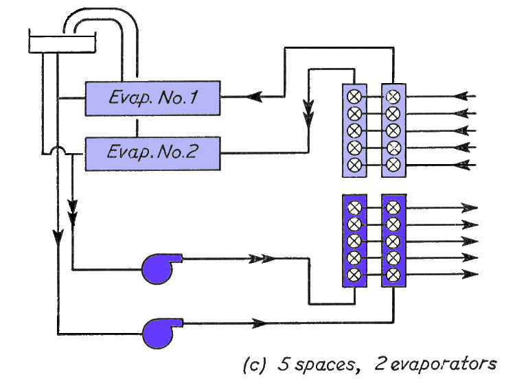
(c) above, shows the addition of a second evaporator, air vent pipes have also been added at this stage.
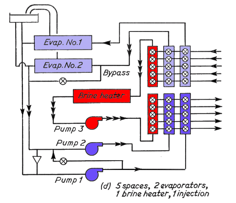
Part (d) above, shows the addition of a third pair of headers served by a brine heater and third pump, so that any battery can be individually defrosted by circulating the warm brine. Also introduced is a brine "injection cross connection from the delivery of pump No. 1 to the suction of' pump No. 2. Brine injection is used so that evaporator No. 1 can assist evaporator No. 2 when No. 1 is set to deliver brine at a lower temperature than No. 2. A further refinement of this injection is the by-pass arranged across the inlet and outlet of evaporator No. 2 so that the cooling, of the brine circulating in No. 2 system can be achieved entirely by injection if desired.
In practice, there also has to be a brine make-up tank. In which solid calcium chloride is dissolved, for topping up the system. An overflow connection from the header tank, a safety pressure relief line from the brine heater, and a sighting connection to which the return from any space can be diverted, are all arranged to terminate over this make tip tank. These have been omitted from the above circuits for clarity.
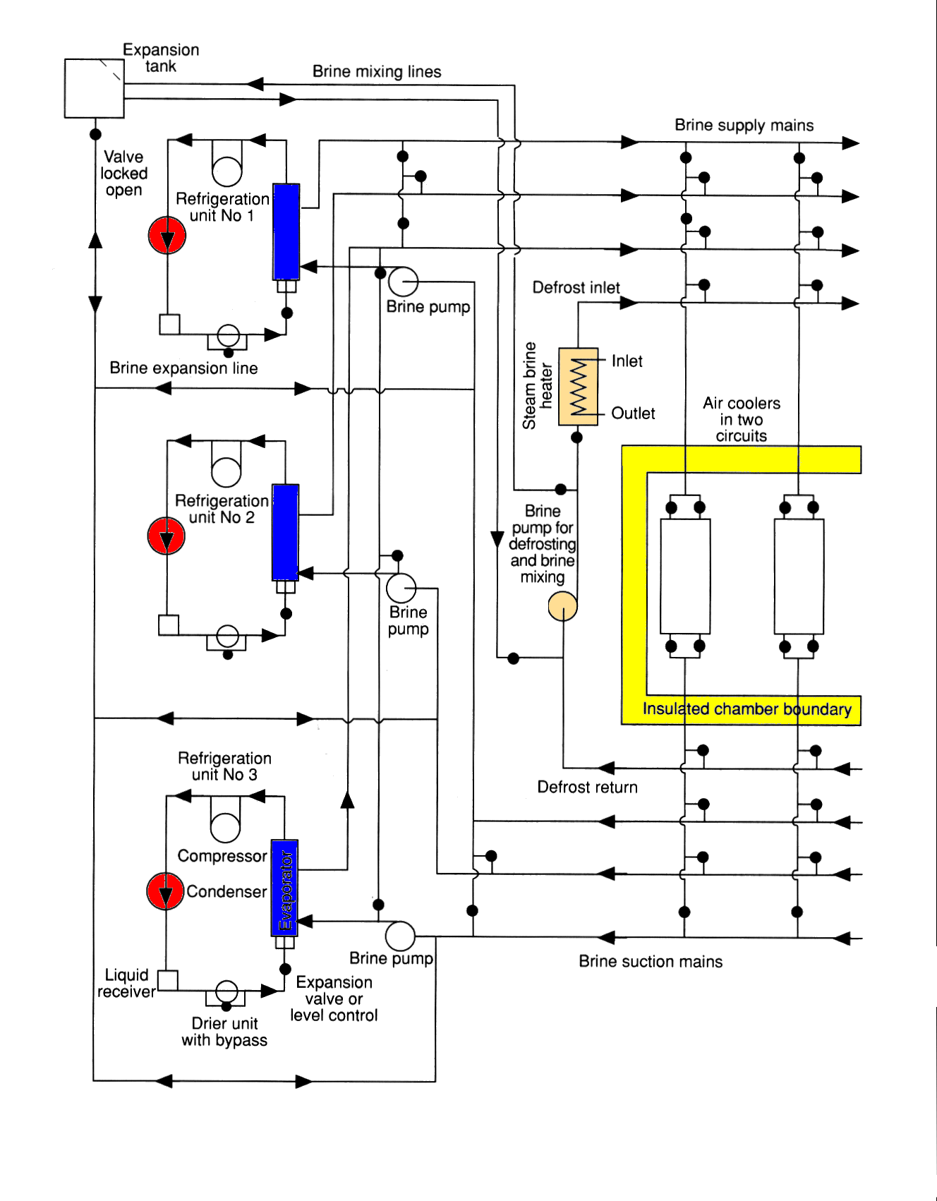
A typical secondary refrigerant system using ammonia as the primary refrigerant in the three independent chillers and Calcium chloride brine as the secondary refrigerant.