Steam Heating systems |
Advantages of Steam Heating over other methods | Differences of Steam from Forced Hot Water Heating Systems | Steam Heating Efficiency Factors | Steam piping | General System Design | Piping Arrangement | Pressure Conditions | Condensate Return | Codes and Regulations | Water Conditioning | Piping Supports | One-pipe Systems | Two-pipe System | Steam Trap Selection | Steam Traps | Good Piping Practice Prevents Water Hammer in Steam Systems | Heat exchanger installation to prevent water hammer | Vacuum breakers | Steam heating Coils
Operation and maintenance of steam heating systems | Common problems with steam heating systems | Water hammer in steam lines | Water hammer in condensate return lines | Maintenance items for service technicians | References and further reading
Steam Heating Systems |
In open - gravity - steam heating systems water is heated to its boiling point 100°C (212ºF) and steam rises by convection through pipes to heat exchangers (radiators) located throughout the building, displacing the air in the pipes and radiators. The steam gives up its heat at the heat exchangers and radiators by conduction to the air and by radiation to the surroundings; condenses and the condensate flows back to the boiler by gravity for re-heating.
It is similar to a hot-water boiler system but operates at a higher temperature. Unlike a hot-water system, there is no pressure-reducing valve or expansion tank. Instead there is an automatic safety control and pressure gauge. A glass water-level gauge shows the water level in the boiler and the low-water cut-off automatically shuts down the boiler should the water level drop too low. The boiler is also equipped with a pressure-relief valve that discharges steam if the pressure exceeds the set pressure. (Around 2 bar (30 to 45 psi) on low-pressure systems).
This type of steam system is a gravity system that is difficult to control and slow to respond to changing demands for heat. It works on the principle of convection – steam rises and cooler water descends.
Advantages of Steam Heating over other methods:- |
Differences between Steam & Forced Hot Water Heating Systems |
Asked whether steam or hot water is the best choice for heating applications. Many factors suggest steam.
Forced hot water systems deliver heat by the partial cooling of a flow of hot water as it passes through a heat exchanger or radiator at the point of use, with typical temperature reduction from 80°C to 40°C (170°F to100°F). In contrast, steam systems deliver heat by condensation of steam into liquid in a heat exchanger at the point of use. The condensing of steam releases 2,257 kJ per litre of water (8,400 BTU per gallon), far more than the 83.72 kJ which are delivered by a litre of water cooled 20°C. This means nearly 30 litres of water must be supplied (and pumped) to deliver the same amount of heat as from each litre of steam condensed in a heat exchanger by a steam heating system.
Distribution
Saturated steam has a heat content some four times that of hot water and readily gives up most of it on condensing. For the same amount of heat, a smaller pipe is required to transfer steam to the point of use than water. As the surface area through which heat is radiated to atmosphere is smaller, so will be distribution.
Weight of fluid
For a given heat requirement, the weight of steam transported is much less than water. This is of particular interest for structural engineer responsible for planning the routing of pipework.
Pumping
As steam condenses it creates a region of low pressure which is subsequently filled by more steam. Unlike water, it requires no pumping.
Surface Temperature
As steam gives up its heat on condensing there is no change in temperature. For hot water to transfer heat it must cool, creating a temperature difference around the system, which does not suit all applications.
Cost
For the same heat requirement, a hot water pipe will be larger than a steam pipe. This adds to the cost in three ways:- More pipework, insulating material and more substantial pipe supports.
Steam Heating Efficiency Factors |
The effectiveness (efficiency) of a steam heating system is affected by:
Steam Piping |
Steam piping differs from other systems because it usually carries three fluids - steam, water and air. For this reason, steam piping design and layout require special consideration.
General System Design |
Steam systems are classified according to piping arrangement, pressure conditions, and method of returning condensate to the boiler. These classifications are discussed in the following paragraphs.
Piping Arrangement |
A steam system operating for air conditioning comfort conditions must distribute steam at all operating loads. These loads call be in excess of design load, such as early morning warm-up and at extreme partial load, when only a minimum of heat is necessary. The pipe size to transmit the steam for a design load depends on the following:
2. The total equivalent length of pipe, in the longest run.
3. Whether the condensate flows in the same direction as the steam or in the opposite direction.
The major steam piping systems used in air conditioning applications are classified by a combination of piping arrangement and pressure conditions as follows:
2. Two-pipe medium pressure
3. Two-pipe low pressure
4. Two-pipe vapour
5. Two-pipe vacuum
6. One-pipe low pressure
One or two-pipe arrangements are standard for steam piping but for commercial and industrial buildings the two pipe systems are more common.
The one-pipe system uses a single pipe to supply steam and to return condensate. Ordinarily, there is one connection at the heating unit for both supply and return. Some units have two connections that are used as supply and return connections to the common pipe.
A two-pipe steam system is more commonly used in air conditioning, heating, and ventilating applications. This system has one pipe to carry the steam supply and another to return condensate. In a two-pipe system, the heating units have separate connections for supply and return.
The piping arrangements are further classified with respect to condensate return connections to the boiler and direction of flow in the risers:
Pressure Conditions |
Steam piping systems are normally divided into three classifications
Pressure ranges for the three systems are:
Condensate Return |
The type of condensate return piping from the heating units to the boiler further identifies the steam piping system. Two arrangements, gravity and mechanical return, are in common use.
'When all the units are located above the boiler or condensate receiver water line, the system is described as a gravity return since the condensate returns to the boiler by gravity.
If traps or pumps are used to aid the return of condensate to the boiler, the system is classified as a mechanical return system. The vacuum return pump, condensate return pump and boiler return trap are devices used for mechanically returning condensate to the boiler.
In a dry return system, the return line in the boiler room is above the boiler water level. With a wet return the return line is below the water level.
Codes and Regulations |
All applicable codes and regulations should be checked to determine acceptable piping practice for the particular application. These codes usually dictate piping design, limit the steam pressure, or qualify the selection of equipment.
Water Conditioning |
The formation of scale and sludge deposits on the boiler heating surfaces creates a problem in generating steam. Scale formation is intensified since scale-forming salts increase with an increase in temperature.
Water conditioning in a steam generating system should be under the supervision of a specialist.
Piping Supports |
All steam piping is pitched to facilitate the flow of condensate. The table below contains the recommended support spacing for piping pitched for different gradients. The data is based on Schedule 40 pipe filled with water, and an average amount of valves and fittings.
RECOMMENDED HANGER SPACINGS FOR STEEL PIPE |
|||
NOM. PIPE SIZE(in.) |
DISTANCE BETWEEN SUPPORTS (m) |
||
Average Gradient |
|||
1% (1 in 100) |
½ % (1 in 200) |
¼ % (1in 400) |
|
¾ |
3 |
- |
- |
1 |
4 |
2 |
- |
1¼ |
5 |
3 |
2 |
1½ |
6 |
4 |
3 |
2 |
7 |
5 |
4 |
2½ |
8 |
6 |
5 |
3 |
9 |
7 |
6 |
3½ |
10 |
8 |
6 |
4 |
11 |
9 |
7 |
5 |
12 |
10 |
8 |
6 |
13 |
11 |
8 |
8 |
- |
13 |
10 |
10 |
- |
15 |
12 |
12 |
- |
16 |
13 |
NOTE: Data is based on standard wall pipe filled with water and average number of fittings. Courtesy of Crane Co.
One-Pipe Systems |
This system is used on small commercial and residential systems. In a one-pipe system, the same pipe is used to distribute steam to various radiators and carries the condensate back to the boiler. The radiators used in this system must be sloped so the condensate flows back through the supply valve. Each radiator has a manually operated vent valve and supply valve.
A one-pipe gravity system is primarily used on residences and small commercial establishments. The steam supply main rises from the boiler to a high point and is pitched downward from this point around the extremities of the basement. It is normally run full size to the last take-off and is then reduced in size after it drops down below the boiler water line. This arrangement is called a wet return. If the return main is above the boiler water line, it is called a dry return. Automatic air vents are required at all high points in the system to remove non-condensable gases. In systems that require long mains it is necessary to check the pressure drop and make sure the last heating unit is sufficiently above the water line to prevent water backing up from the boiler and flooding the main. During operation, steam and condensate flow in the same direction in the mains, and in opposite direction in branches and risers. This system requires larger pipe and valves than any other system.
| TWO-PIPE SYSTEMS |
With a two-pipe system, the steam is supplied in one pipe and the condensate returned by gravity to the boiler by another. The radiators do not have an air-vent valve, instead they are equipped with steam traps that allows the air bound in the radiator and condensate to flow in the return pipe but closes on steam contact. (A two-pipe steam system can usually be converted to a forced circulation hot-water system).
A two-pipe gravity system is shown below. This system is used with indirect radiation. A gravity system has each radiator separately sealed by drip loops on a dry return or by dropping directly into a wet return main. All drips, reliefs and return risers from the steam to the return side of the system must be sealed by traps or water loops to insure satisfactory operation.
Two pipe gravity system
Two-Pipe low Pressure System |
This system is used for commercial, air conditioning, heating and ventilating installations.
Two-Pipe Vapour System |
This system is used in commercial and residential installations.
Two-Pipe Vacuum System |
This system is used in commercial installations.
| Two-Pipe Medium Pressure System |
This system is used mostly in plants and occasionally in commercial installations.
Two-Pipe High Pressure System |
This system is used mostly in plants and occasionally in commercial installations.
Steam Trap Selection |
The use and selection of steam traps, and condensate and vacuum return pumps are presented in this section.
The primary function of a steam trap is to hold steam in a heating apparatus or piping system and allow condensate arid air to pass. The steam remains trapped until it gives up its latent heat and changes to condensate. The steam trap size depends on the following:
1. Amount of condensate to be handled by the trap.
2. Pressure differential between inlet and discharge at the trap.
3. Safety factor used to select the trap.
Amount of Condensate |
The amount of condensate depends on whether the trap is used for steam mains or risers, or for the heating apparatus.
The selection of the trap for the steam mains or risers is dependent on the pipe warm-up load arid the radiation load from the pipe. Warm-up load is the condensate that is formed by heating the pipe surface when the steam is first turned on. For practical purposes the final temperature of' the pipe is the steam temperature. Warm-up load is determined from the following equation:
![]()
where:
C1 = Warm-up condensate
m = Total mass of pipe
tf = Final pipe temperature, °C (steam temp)
ti = Initial pipe temperature, °C (usually room temp)
C = Specific heat constant for wrought iron or steel pipe
h1 = Latent heat of steam, kJ/Kg. °C (from steam tables)
T = Time for warm-up [s].
The radiation load is the condensate formed by unavoidable radiation loss from a bare pipe. The radiation load builds up as the warm-up load drops off under normal operating conditions. The peak occurs at the mid-point of the warm-up cycle. Therefore, one-half of the radiation load is added to the warm-up load to determine the amount of condensate that the trap handles.
Steam Traps |
The open float, or bucket, type of steam trap, in which the discharge is controlled by some form of float or bucket, is used to drain condensate from piping, heaters and other equipment. In another type the discharge is controlled by expansion of the metal forming part of the trap; a third type, the thermostatic trap, controls the discharge by expansion of the vapour from a volatile liquid enclosed in a bellows type element, and is used to drain steam radiators, thermo-ventilating heating units, galley and laundry equipment, etc.
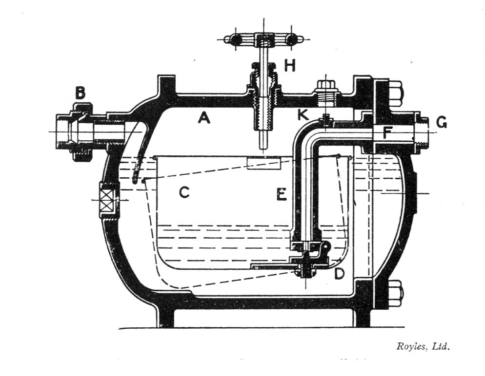
"SYPHONIA RAPIDE" Trap of the open-float type, designed to discharge the condensate as it is formed.
The body A of the trap is provided with a union B on the inlet, through which the condensate enters and is diverted downwards by a baffle to prevent it splashing directly into the open float C. As the water accumulates it eventually overflows into the float, and, destroying its buoyancy, causes it to sink, opening the hinged valve D to which it is attached. The pressure in the body of the trap then forces water from the inside of the float up the discharge pipe E to the outlet F, which is fitted with an oval counter flange C. When the float is about two-thirds empty it becomes buoyant again and rises sharply to close the valve, which is thus always water-scaled. The illustration shows the trap complete with the blow-through attachment H. An air vent K is also fitted in the top of the discharge pipe to by-pass any air which may tend to accumulate to the outlet. It may be adjusted if necessary by removing the plug on the body immediately over it.
Good Piping Practice Prevents Water Hammer in Steam Systems |
One of the most common complaints against steam heating is that a system sometimes develops a hammer-like noise commonly referred to as water hammer. It can be very annoying. More importantly, it can indicate a condition which could produce serious consequences including damaged vents, traps, regulators and piping.
There are two types of water hammer that can occur in steam systems:-
One type is usually caused by the accumulation of condensate (water) trapped in a portion of horizontal steam piping. The velocity of the steam flowing over the condensate causes ripples in the water. Turbulence builds up until the water forms a solid mass, or slug, filling the pipe. This slug of condensate can travel at the speed of the steam and will strike the first elbow in its path with a force comparable to a hammer blow. In fact, the force can be great enough to break the back of the elbow. Steam flowing in a system at 50m/s is travelling at over 100 miles per hour. The slug of condensate can reach the speed of the steam flow.
The second type of water hammer is actually cavitation. A steam bubble forming or being pushed into a pipe completely filled with water causes this. As the trapped steam bubble looses its latent heat, the bubble implodes, the wall of water comes back together and the force created can be in severe. This condition can crush float balls and destroy thermostatic elements in steam traps. Cavitation is the type of water hammer that usually occurs in wet return lines or pump discharge piping.
A properly piped steam system should not produce water hammer of either type.
Vacuum breakers |
Most steam to water heat exchangers provide a tapping in the shell to allow installation of a vacuum breaker. The vacuum breaker allows air to enter the shell if a vacuum is induced. Failure to install a vacuum breaker will allow the heat exchanger shell to operate at a negative pressure which may cause condensate to hold up in the shell causing water hammer.
Steam systems offer a lot of advantages for distributing heat in large facilities. When the systems are properly installed they provide years of trouble free and noise free operation.
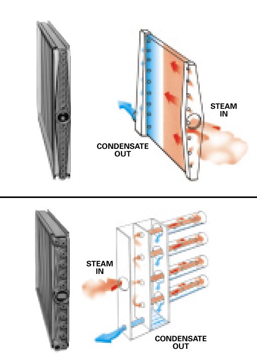
Steam heating Coils |
A steam heating coil – note how the tubes are inclined down to aid condensate removal.
|
|
Operation and maintenance of steam heating systems |
Record Keeping for Operating Efficiency
If you're going to control a cost you must have records of it first. It is important to record the amount of fuel used with the heating degree-days recorded in the same period (from weather records or fuel suppliers). In addition to weather records, building operating hours and thermostat settings during operating and non-operating periods should be recorded so heating system operating characteristics can be 'learnt' which in turn can allow the system to be adjusted in readiness to meet actual heating requirements.
Common problems with steam heating systems:- |
The air can't get out of the system fast enough
Where there is air, steam won't go. It is very important to quickly remove the air from the system allowing the steam to travel to the radiators. Main vents are vital to proper distribution. Make sure there are adequate vents on the steam main (usually in the basement). Replace or add vents as needed.
The boiler is piped incorrectly
A modern steam boiler requires the ‘near boiler’ piping to help produce "dry" steam for the system. The boiler's steam chamber is smaller and the supply riser holes are smaller, and this affects the boiler's ability to separate the water from the steam, so the manufacturer wants to use the header and equalising line piping to "catch" this water and prevent it from heading out into the system with the steam. When piped incorrectly, the steam is forced to carry water with it as it leaves the boiler. Naturally, the water condenses the steam before it reaches the radiators.
The boiler is undersized or under-fired
A steam boiler's job is to produce enough steam to fill the entire piping system and all the radiation. The job of the cold pipes and cold radiators is to condense this steam, but if the boiler can't produce enough steam to overcome this mass of cold iron, the steam will not be able to make it out to the furthest radiators. This is why you must size the boiler to the connected load and then make sure the burner is fired to that load.
Boilers were typically made with heavier-gauge cast iron or steel and may last about 50 years – some as old as 80 years!
The steam traps have failed
Two-pipe systems have radiator traps and float and thermostatic traps. Their job is to pass air and condensate into the return piping while preventing the steam from getting past the radiators and ends of the mains. When these traps fail in the closed position, the air can't get out, so the steam can't get in. But when they fail in the open position, the steam passes into the return lines. Once there, it pressurises the returns to the same pressure as the supply lines, and with no difference in pressure, the steam stops moving. You have to make sure the steam traps are working properly for the system to operate efficiently.
The pipe insulation is ineffective
To retain heat, steam pipes should be well insulated. Steam mains should be well insulated to ensure the heat is provide to the building in the required place (not in boiler rooms and service ducts, etc).
Where insulation is inadequate the pipework acts as a radiator, this additional load then condenses the steam before it can reach the most distant radiators. Inspect the condition of the pipe insulation on an annual basis. If it is inadequate, damaged or loose fitting it should be replaced – usually by insulation specialists, particularly on larger systems.
In older systems this insulation is often asbestos. If this is suspected, under no circumstance should this covering be disturbed, it should only be handled by specialists with special containment equipment.
The steam pipes are pitched incorrectly
When originally installed, steam mains and horizontal run-outs had certain pitches to them that allowed the condensate and steam to co-exist in the same pipe. Over the years, the building settles and pipe hangers loosen up, changing the pitch of the pipes, and allowing condensate to collect in pockets along the piping. These puddles will condense the steam as it passes by, creating uneven heat throughout the building. Make sure the steam mains and run-outs maintain proper pitch
The quality of the steam is bad
If the boiler water is dirty or has a film of oil on its surface, the boiler will make "wet" steam. Because water droplets "rob" the steam of its latent heat, steam is condensed in the piping before it reaches all the radiators. Check the quality of the boiler's water by looking at the boiler's gauge glass. When the boiler is making "dry" steam, the top portion of the glass will be dry. While the boiler is operating, raise the water line to within one inch of the top of the gauge glass if water pours over the top of the gauge glass, the boiler water is dirty and the entire system should be flushed out.
The wet return lines are partially plugged
If the steam system has wet returns and the complaint is uneven heating, make sure the returns aren't plugged. If they are, the condensate will back up the return drips trying to overcome the additional pressure drop created by the plugged returns. Condensate will back up into the main vents closing them off before all the air is removed from the mains, and this can create very uneven distribution of the steam throughout the system.
Someone has set the pressure control too high
Radiator steam vents have a rating that's known as "drop-away" pressure. This rating has to do with the maximum system pressure at which the vent's float can drop down to re-open when the steam condenses in the radiator. If someone raises the pressure control setting beyond the vents "drop-away" rating, it is possible to close the entire radiator vents in the system, and this leads to uneven distribution of heat throughout the building. Always check the pressure control setting on the boiler as well as the "drop-away" rating of the vents in the system. Typically, steam heating systems were designed to operate at a maximum of just a few pounds.
The boiler cycles off on low water
This is common with modern replacement boilers that are much smaller and have less water volume than older boilers. The symptom occurs when the boiler initially fires and begins filling the system piping and heat exchangers with steam. As the steam leaves the boiler, the water level begins to drop, eventually the low-water cut-off turns the burner off. The boiler cannot fill the system with steam, as it does not have enough water capacity. The solution is to install a boiler feed package. These packages add more water volume to the system and are controlled to maintain the most efficient operating level in the boiler.
Water hammer in Steam Lines |
Water hammer in steam lines in normally caused by the accumulation of condensate as described above.
Important installation details to prevent water hammer in steam lines include the following.
- Steam pipes must be pitched away from the boiler toward a drip trap station. Drip trap stations must be installed ahead of any risers, at the end of the main and every 300 to 500 feet along the steam piping.
- Drip traps must be installed ahead of all steam regulator valves to prevent the accumulation of condensate when the valve is in a closed position.
- "Y" Strainers installed in steam lines should have the screen and dirt pocket mounted horizontal to prevent condensate from collecting in the screen area and being carried along in slugs when steam flow occurs.
- All equipment using a modulating steam regulator on the steam supply must provide gravity condensate drainage from the steam traps. Lifts in the return line must be avoided.
In most installations, water hammer in condensate return lines is caused by steam pockets forming and imploding. Most frequently, the cause is a rise in the discharge line from a trap or a high-pressure trap discharging into a low temperature wet return line.
A lift in the return line after the trap will cause water hammer because the temperature of the condensate leaving the trap exceeds 100 °C (212 °F). The high temperature condensate flashes causing steam bubbles to form. As these steam bubbles are pushed into colder condensate in the return piping, they implode and cause water hammer. The water hammer will normally be worse during start up due to the cold condensate lying in the return piping. As the temperature of the return line increases above 100 °C (212 °F) the water hammer often stops. Many industrial applications install lifts to avoid installing additional condensate return systems. When installing a lift, the most commonly used trap is an Inverted Bucket trap since the open bucket design tolerates moderate water hammer without damage to the trap. A check valve is normally installed after the trap discharge when a lift is required. The check valve helps isolate the trap from the water hammer forces and prevents back flow of condensate when the steam supply is secured.
When a trap discharges into a wet return line, flashing will occur. Again, these steam bubbles implode causing water hammer. This condition is often found where a high-pressure drip trap is connected into a pumped return line with lower temperature condensate. Older versions of the ASHRAE guide showed the use of a diffuser pipe to break up the high temperature condensate to reduce the size of steam bubbles that occur. The guide showed welding a pipe tangentially in the return line and drilling 1/8 inch holes at least 1 inch apart. Other methods include using a heat exchanger to blend the two temperatures or the use of fin tube radiation to cool the trap discharge. The most common method used is to install a flash tank on the drip trap discharge allowing the condensate to flash to 100 °C (212 °F) and then pumping the cooled condensate into the common return line.
Important installation details to prevent this type of water hammer are listed below.
MAINTENANCE ITEMS FOR SERVICE TECHNICIAN |
Boiler – Should be drained once a year when the boiler is cold. Close the water inlet valve, unscrew the pressure relief valve and attach a hose to the drain cock to lead the water to a floor drain. Fill the boiler about one-third with water and repeat the process. Add a rust inhibitor through the safety valve and replace the valve, close the drain and fill the boiler to the proper level.
Safety valve – Located on the top of a boiler, the valve allows steam to escape if the pressure in the exceeds a pre-set safe level. Test the valve every month during the heating season by depressing the handle. If no steam comes out or the valve does not completely close, replace the valve.
Steam pressure gauge – The pressure in the boiler should be between 2 to 10 psi. If the gauge indicator is not in this range, call for service.
Water level gauge – The valves at each end of the gauge should be opened once a month. The water level should be in the middle of the valve. If water is not visible, shut off the boiler, let it cool and add water by opening the fill valve on the water inlet pipe. If your system has an automatic water fill valve, call for service.
Low-water cut-off – Open the blow-off valve at the bottom of the low-water cut-off once a month when the system is off to drain off sediment-filled water that could clog the cut-off.
Maintenance of Traps - Every trap should be tested daily and repaired as soon as a leak is found. An inefficient trap wastes a great deal of steam, and economy can be obtained only with absolutely tight valves. Traps should not be subjected to pressures higher than those for which they are designed.
The principal causes of inefficient working are leakage from a discharge valve scored by erosion or dirt, punctured float or bucket, sediment in the bottom of the trap, a too small or improperly seating discharge valve, or open or leaky by-pass valves.
If a trap, serving a line containing very little condensate, does not accumulate enough water to close, cold water poured on the trap will often cause sufficient condensate. Otherwise, the trap can be shut off and primed with water.
For low steam pressures, traps with large discharge valves are preferred, because the steam is more highly saturated and condenses more rapidly giving a proportionately larger volume of water. For high steam pressures, owing to the small amount of water and high velocity of ejection, smaller discharge valves can be used.
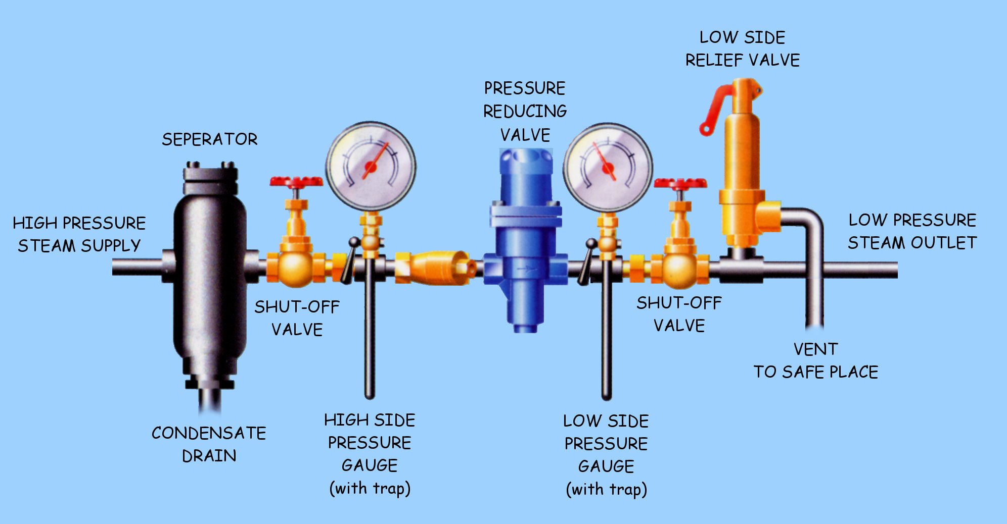
Pressure reducing sets. |
References and further reading. |
Handbook of air conditioning design, Carrier Air Conditioning Company. McGraw Hill Book Company.
Marine Auxiliary Machinery, W. J. Fox, Newnes-Butterworths. ISBN 0 408 00028 7
Article by Joe Mower; Product Line Manager for ITT Hoffman and McDonnell & Miller.
McDonnell & Miller / Hoffman, CounterPoint, February 1998 by ITT Industries.
Kent’s Engineer's Handbook, Power Volume, Eleventh Edition, John Wiley & Sons Publisher.
American Society of Heating, Refrigerating and Air Conditioning Engineers (ASHRAE)
The Heating, Refrigerating and Air-Conditioning Institute of Canada (HRAI).